Tuesday, January 19, 2021

E-Magair EICAD

RV14 Build December 

EICAD

Right when I was going to order my engine Vans announced the new YIO-390-EXP119 motor for the RV14! Yeah less weight, more power, reduced drag on the cowling re-design! Booo more cost. Well I went for it, but I decided not to go for the thunderbolt version because of cost. Since it was a standard motor Lycoming would only ship it with 1 Emag and a standard Impulse Mag.

I called Emag and ordered the other Pmag, plus the lycoming gear, harness, and spark plug adaptors. I spent a ton of time on the forums trying to find the best settings for the IO-390 and Bill at EICommander was super helpful! Bill@repucci.com. Even though I wasn't installing his unit he emailed me back and forth to help me get the harness connections correct and recommend settings.

This is the wiring guide from EICAD program that I help use to understand how to wire my DB9. This drawing I found a little confusing because of the location of the numbers on the DB9. But the pin numbers are correct and just go with those.

This is how I ended up wiring mine, except I went with a 4C shielded cable and used a dedicated ground wire and not the shielding as a ground, but the pins are the same.

My wire color and pin out on the DB9
Pin 1 = N/A
Pin 2 = Blue
Pin 3 = Green
Pin 4 = N/A
Pin 5 = Orange
Pin 6 = White
Pin 7 = N/A
Pin 8 = N/A
Pin 9 = N/A


I made one for each Pmag and plan on installing them through the firewall and behind the subpanel to make changing setting or checking settings easier, or if I want to upgrade to an EICommander.

These are instructions I found on Vans Airforce


Bills recommended way of setting up the Emad for a IO-390.

I had some trouble getting V3 from Emag. THey wouldn't come out and say it but I think they only want to send out version 4. The problem with version 4 is that you can't put in negative values for Advance shift and know that it took it correctly. It will never read a negative value when you restart to check, V3 will.

Version 3 to check the changes are hard to find unless you know someone with it. I found it web.archive.org and searching around, but this might help.

I make the changes with V4 then check them with V3, take a screen shot so I know for the future.

EICAD 1.5 Man Hours


Section 46B: Wheel Fairings - Rework and bodywork

RV14 Build December 

Wheel Fairings

I had drilled the outboard main wheel fairing brackets because the called for AN3H3A Bolts wouldn't fit in easily. Turns out this was a mistake, after all the work on the wheel fairing there was a relatively easy enough rotation where the fail end would move up and down about 2-3".

So  I decided since I had the time waiting on the FWF kit to order new brackets are redo the work. I did these 1 side at a time, because I wasn't sure how much it would make a difference. Spoiler it removed almost all the movement and I ended up re-working both sides.

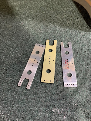
New Brackets. About to be deburred and primed.
RV14 Build

The fit is very tight, I would say the bolts tap there way through.

After installing the brackets it was just a matter of going through the process again.  I used a dremel sanding wheel to sand out the Flux that was on the inside of the 2 halves of the wheel fairing. Before sanding.

This allowed the new bracket to to float on it while I reset the front and back wheel fairing height. What was helpful was the forward top screw hole on both inboard and outboard of the fairing location was set with the holes already drilled and I could use this to keep the "toe in" angle matched then I leveled the airplane and measure the distance the rear bracket hole is off from level and transfer that to the wheel fairing.

What ending up being level was about and even 8" off the ground for me after adjusting for the bracket hole location.

I did drop a plumb bob off a fuselage rivet line to the ground and transfer that line to the wheel to make sure the longitudinal axis was still aligned with the fuselage and thus the airflow. This one was more of a check than setting it. Since I used the top forward hole on both the inboard and outboard of first fairing mounting attempt this orientation should not have/didn't change. Also at this stage I located and drilled the other mounting holes. I don't know if this is what they are for but the kit comes with round magnets that work perfect for locating holes in opaque panels. 

I then put tape over the bracket and added flux to the inside of the fairing to set the bracket into.


i used pan head screws to hold the fairing while the flux was setting up.
After It set up I countersunk the holes and put in the correct screws. Since I still had time to kill before my next kit I decided I didn't really like the way the halves matted after being secured to the gear. There was a unevenness between all the screws.

I had been working with the chop cotton flux so much I just went with it for the "filler" I should have used micro-balloons and did on the other side....it would have been way easier to sand. I taped off the front half to prevent flux from sticking to it, scuffed up the gel coat and laid on the flux.

After sanding forever I realized I needed more filler to transition smoother and this time I used micro. Much easier to sand.

Repeated for the other side.

Finally 2 wheel fairing that I am happy with and hopefully will be easy for the painters to finish and make perfect.


Section 46B: Wheel Fairings 18.5 Hours

Friday, November 20, 2020

Section 46B: Wheel Fairings

RV14 Build September

Wheel Fairings

You start out by trimming the fairings to the scribe line. I used a dremel cutting to get close and finished with sand paper. I eventaully learned just to used 60grit out of the gate to remove material quicker.

There is A LOT of trimming and trial fitting in this stage. You also sand the mating surfaces to try to get a smooth transition. I spent a lot of time on this and it probably helped, but when you mount the fairings they are squeezed a bit and it flexes the shape which distorts this work, so don't kill yourself on this now.

Definitely get some sanding blocks to keep your lines straight, or smooth at least.

Finished interior trim, for now. You do more after mounting onto the wheel.

Tring to get the seems to lay flat.

Using a shop light to find the drill holes in the bracket. This is not as simple as I thought it would be. Section 5 has some notes about how to use magnets and I found some luck with this technique. 

Plans then have you measure and cut the axle holes.

I used a hole saw and a dremel bit for this. Finished with sand paper.


Starting on the gear leg fairing hinges.

Checking the gear legs for twist. 1 more mine had a slight twist so i followed the plans to remove it. Now its straight, but I would find out later this would put pressure on the hinge and pin and make the install for the pin difficult.

Cleking together before drilling for rivets

The plans tell you where to place the hinges. I think I was a little aggressive on this, the hinges pull the parts together in a way that bend the fiberglass and separates the trailing edge. Ill be fixing this with FLUX most likely when the time comes.

Drill your first pilot hole.

Match drill undersize the fairing.

Clamp the other end while doing this.

Then install the hinge on the inside and final drill to #40.

Trim the fairing to the scribe line.

Primed the hinges.

Counter sink and rivet.

2 completed leg fairings, at least up to this point.

These U-00002 brackets I had a hard time getting the bolt through to I enlarged the holes with #19 bit and the bolts went in great, but it added some rotation ability to the bracket. Which way after the fact I will find out adds about .5" of movement to the rear of the wheel fairing up and down.

Anyway. I leveled the airplane and then used a level to find out where the bracket sat. You figure out how much the level needs to go up and measure that once level. Then transfer that distance to the hole pattern on the fairing.

Next you match the wheel angle so you can transfer this to the fairing as well.

Then I used a plumb bob to drop a straight rivet line on the floor and a T-square and level to transfer that line closer to the wheel.

I didn't get a photo of it. But you drill the outboard, top, forward hole and inset a cleko. Then the distance the level was off you drill the outboard, top, rear hole below the marked location in the fairing. This should set up and down rotation and you can measure and drill the bottom 2 holes and cleko. Once they are installed with clekos you measure the tip and tail to align the fairing to the flight path/ rivet line you transferred to the floor and to the level.

You use the center of the trailing edge as the measuring point.

And the tip of the nose. Then you locate and drill the inboard nut plate hole locations and this holds the longitudinal orientation. Easy to say hard to do. I found that the round ball magnets in the plans come in handy here for locating the holes.

Next you tape the bracket and I added mold release wax.

Mix up some flux and add it to the inside of the wheel fairing and screw the fairing in place, but not all the way.

Allows the flux to spread out and give a larger/ smoother mating surface.

Once this is cured, you remove the fairing and install nutplates for the 2 halves of the fairing. The bottom 2  clekos I found are too low to the ground to get a screw driver under to remove the screws. I would think about moving those up a bit.

The install is complete for now. I need the lower cowling to do the rest of the fairings.

I did notice after that the fairings had some rotation issues of about a half inch do to the brackets I drilled. So I ordered now brackets and will try this all again.


Section 46B: Wheel Fairings 22 Hours

Before Start and First flight testing

 R14 Build August & September 21 Testing Getting into the fun stuf!! Putting gas in for the first time. Have the airplane up to get 15 d...