Showing posts with label FWF. Show all posts

Wednesday, September 1, 2021

FWF OP-62 Sniffe tube and Tunnel flap

 RV14 Build June 21

I ordered the pre-made sniffle tube as part of my aircraft specialty hose kit. Made this install very easy.

Another view of the sniffle, I did change to the one way valve on the bottom of the intake first.

Tunnel flap all together and chase tape installed.

Tunnel flap screwed into place.

Getting the cable length correct was a bit of a pain in the ass. Very tight space.

Finally got a cable that I like.


EXP 119 Mods 11 Man Hours 

FWF Routing Engine Sensors & Pmag timing

RV14 Build May & June 21

Getting the CHT wired in, had to test it lol!

All the CHT are in. I used my heat gun to test that they are wired to the correct cylinder. All good!

We have manifold pressure! 

Another 14 was having trouble with fluctuating manifold pressure readings and I read that Garmin recommends using a PS-8G so i went ahead and installed one right at the base of the sensor

After the restrictor I install the elbow and pressure line.

The Oil pressure and Fuel pressure sensors are installed. Just have to trim the zip ties once I commit to this final placement.

View from below of the same sensors.

Routing the CHT wires and securing them

Secuting the #1 CHT and EGT wires.

Keeping the rear EGT wires long enough to reach the front cylinders to help with future troubleshooting.

The EGT holes are already drilled you just have to open them up a little more. The plans have you use a #30 i think, but it wasn't enough to I let the bit wobble in the hole a little to make it slightly bigger. This gave me a nice tight fit for the EGT sensor. The sensor cables are looped to prevent fluids from wicking up the line.

View of the EGT sensor sitting flush on the exhaust.

Right side all wired and routed.

Left side all wired and routed.

Ive never used one, but I started to worry about needing an alternate static source so Im going to install this valve.

The valve really wants to spring open to I purchased a red flip up guard to help keep it closed

The switch is mounted behind the G3X screen on the subpanel.

Man buss with wire protectors.

The automotive wire harnesses are fatter than standard lycoming. I used a reamer to open up the mounting baffle pass throughs.

Tight and snug fit now.

Programming the PMAGS using the EICAD program. For a IO-390 you need to find version 4 to set the timing but use version 3 to read it and make sure it took. There is a glitch in the system for 4 when you use a negative value for advance shift it will display it as 12.6.

My initial settings are to fire at 20BTDC all the time with no advance to help with CHT temps and diagnosis if there is a problem I know its not advanced timing causing it. You can see on this version 4 the advance shift is displayed at 12.6 even though I put it in at -7.

Using the back to the spinner ring gear to set TDC

Line it up with the case.

FWF Avionic wiring 10.0 Hours
Pmag timing 3.0 Hours


Reiff heater Install

 RV14 Build June 21

FWF Wiring Reiff

I wanted to install the full REIFF XP heater kit, but on the IO-390C sump there isn't a flat place to install a sump heater. I decided to keep the cylinder bands though. They are very easy to install. Just slide around the base of the cylinder and go together like a hose clamp.

After they are clamped I used safety wire to prevent the screw from backing off and loosening the clamps.

Close up view of the safety wire.

Securing the wires with zip ties per the REIFF plans.

Safety wire and potting the entry hole with RTV. The green wire is a case ground. I did have to trim the baffle on the #2 cylinder so it would sit flat and not dig into the heater band.


Reiff 1 Hour


FWF OP-62 Exhaust

 RV14 Build June 21


Working on the exhaust hangers. You cut the metal to length then squeeze 1 end to cause it not to be round a have a flair. This is what hold it into the rubber tube.

Kind of see the flair in the photo.

This is how it installs on the exhaust tube.

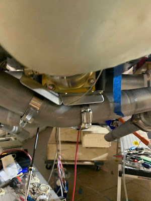
Getting the exhaust all lined up was a bit of a puzzle. I finally was able to make sense of it. Used the antisieze called out in the plans in all the joints.

When I removed the caps covering the exhaust ports they were filled with oil

Exhaust all mocked into place.

Flanges are torqued

Now that I know how the pipes run Im installing the fuel flow transducer. 

I made a spacer to get the transducer to sit level and not bank against the oil sump.

Double heat shield for the fuel injector.

Tighten the exhaust mounting bolts until they bottom out.

Time to start in on the cabin heat.

First thing you do is cut the tubes to length

There was a lot of trial and fit in this stage. Working the metal wire back as needed per the plans.

Getting the hoses clamped into place. I used RTV anywhere that those hoses came in contact with another surface.

RTV the corners of the Co-Pilot cabin heat inlet. This forces the air to stay in the tubes or enter the cabin here. If it stays in the tubes it flows over the the pilot side where it enters the cabin or flows overboard.

One of the 2 exhaust shrouds on the right side of the photo.

Better view of the smaller exhaust shroud, just the the hose clamps.

Exhaust 8.5 Hours


Before Start and First flight testing

 R14 Build August & September 21 Testing Getting into the fun stuf!! Putting gas in for the first time. Have the airplane up to get 15 d...