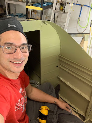
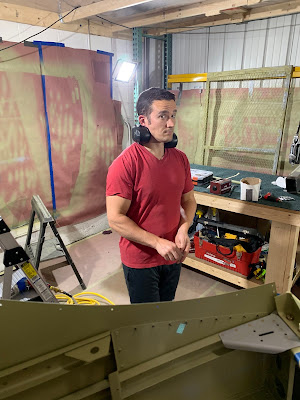
This is my journey to build an Vans RV14 from plans. With the exception that I have later decided to order the RV14 Quick Build Wing. Building mostly alone I was worried about riveting well do to the large size of the wings.
Labels
13-16QBW
21-22QBW
Access Panel Installation
Aft Fuselage
Aft Fuselage Attachment
Aileron & Elevator Systems
Aileron Actuation
Aircraft Specialty
Antenna
Antisplat
Attachment
Avionics
Avionics Panel
B&C Filter
Baffle
Baggage Area
Bottom Wing Skins
Canopy and Window
Canopy harness
Common Fuselage Harness
Control Cables
Cowling
Deydrator
EICAD
Electrical
Eletric Aileron Trim
Elevator
ELT
Empennage
Empennage Fairings
Engine Installation
Exhaust
Exp119 Mods
finishing kit
Firewall
Flap Actuation System
Flap Position Sensor
Fuel and Oil System
Fuel System
Fuel Tank repair
Fuel Tanks
Fuselage
FWD Fuselage Lower Structure
FWD MID FUSE Side Structure
FWD MID Fuselage Bulkheads
FWF
GAP 26
Garmin AutoPilot Servos
Horizontal Stabilizer
Interior Topcoat
Landing Gear & Engine Mount
MID Fuselage Lower Structure
Miscellanea
Move
OP62
Outboard Leading Edge
Paint
parking brake
PitoStatic
Programming
QBW
QBW Corrosion
QBW Re-Work
Reiff
Roll Over Structure
Rudder
Rudder & Brake System
seatback's
shop
Skybolt
Spinner and Propeller
Testing
Upper FWD Fuselage
Vertical Stabilizer
Wheel Fairings
Wing Attachment
Wing Rebuild
Wing Systems Routing
Wing Tip
Wiring
Saturday, February 15, 2020
Thursday, February 13, 2020
Section 31 Fuel System
RV14 Build January
Fuel System
I was back and forth on this, and still might be, I can buy a prebend kit of fuel lines for $300ish but I wanted to do the work and learn it so I bought an imperial tube bender, parker flair tool, and a pipe cutter. All together it was about half of prep bend it.
The fuel pump and filter, have to crimp on the ground insulated connector ring. I don't have a good picture but I also installed the fuel line brackets, there was some clearance struggles with the pop riveter, but I used the trailing edge V shaped piece "tool" the plans have you make for the elevator to get in the tight spots. Liz came to the shop and build the fuel selector!
The plans have diagrams you can use to match your bends too, but they use a 1 inch radius and my new bender is 1.5. Reading the directions for the bender is confusing at best. Lots of trial and error.
Finally have tubes that basically match the plan dimensions, now time to flair!
And this is wear my lack of experience bites me. The soft metal is getting torn up by the flairing tool.
The bur left by the cutter is falling apart and getting pressed into the flair.
Yeah, definitely not going to work.
Ordered new tubing, after some research it seems if I debur the tube and keep the flair tool WELL lubricated the flairs will come out better. I am going to practice on the old tubing for a bit.
New technique looking MUCH better, now I just need to courage to try it on the new tubing!
Fuel System 6.0 Hours
Section 36 Aileron and Elevator Systems
RV14 Build January & February
Aileron and Elevator Systems
I thought I could install the push rods before I joined the empennage and the fuselage together to I prepped everything. Once I saw how I was going to have to be in the airplane to do some of the riveting I didn't want to have the push rods in the way so I didn't install them, but I did install some of the brackets.
I taped the end of the tube and poured primer down them to prime the insides.
It worked really well, left a heavy coat though, if weight is a concern maybe not the best method. I wanted to anodize them but I couldn't find a shop that would do small work.
Push rod tubes outside primed.
The template that came in the plans was a little small for the tubes, probably because the primer was too thick, so I used a black piece of paper marked the diameter and divided by 6 to find the drill holes.
Drilled the tubes
Had a little trouble with the tightness of the fit because the primer inside the tubes was too thick. Ran to harbor frieght got a heat gun and I was able to pull the parts apart again, sanded down the primer, LIGHTLY sprayed self etching on the metal and then reinstalled the end caps and the push rod bearings.
I was going to install the pushrods with the trim motor and bracket but them I was worried the rod would be in the way during mating the empennage to fuselage. But I thought I could install the bracket and motors anyway......wrong.
The plans have you install the pushrod on the bracket then inset the rod through the bulkhead and install the bracket.
With the empennage and fuselage together you can't get the pushrods through the bulckhead the opposite was the plans intended because there is a cross members in the fuselage that blocks it. So I have to pull the pitch trim motor and bracket to install the push rods. What I tried to do to save me work was a waste and added work! Dang it, oh well.
Aileron and Elevator Systems 10 Hours
Section 56/58 Garmin Auto Pilot Servos
RV14 Build January & February
Garmin AutoPilot Servs
This was over different work periods, but I have enough now that I think it made sense to make a post about it.
2 Garmin GSA28 Servos and the yaw dampener attachment arm.
My brain wasn't working this day and at first I installed the yaw arm upside down on the servo and had to remove and flip it, Here it is currently on and the servo motor installed in the empennage.
View of the yaw servo back to front.
Getting the pitch servo on.
Working on running the wires. I have some wire bundle lacing from earlier in life in my tool bock and am finally making good use of it! Really helps manage the wires better.
Trying to figure out how I want them to run.
Went to an EAA electrical workshop! This was amazing I would highly recommend it to anyone who wants some hands on experience using the tools to make wiring harnesses and install connectors.
The 2 wires that are loose with pins on them come from the wiring harness that is part of the empennage kit and run back to the pitch trim motor. From looking at the master wiring harness diagram from the Vans website they are suppose to connect into the pitch and yaw harness. Ill do my best to explain below.
The diagram has the loose wire with pins, red arrow, run through the grommet below the mini-molex connector and into the molex connector coming from the common fuselage harness, yellow arrow, represented by the red box. The "red box" molex and the molex in the picture connect and boom the wires are connected to the pitch motor.
From the harness diagram the 2 wires are highlighted.
From the pitch diagram the wires they connect to in the pitch harness are highlighted.
All this said leads me to the 2 issues. 1 according to Garmin the wires come "from" the pitch servo "to" the trim motor and should be shielded, for this I called Stein and they said it was a revision to the G3X manual and Vans specs the harnesses and thinks not doing shielded wire in this installation is ok. 2. The wire were too short to wrap out through the bulkhead and into another connector. So I used my new found electrical knowledge bought a bunch of tools and a label maker and industrial labels cut the wires coming from the servo added a 2 pin molex to them and trimmed the loose wires added pins and the molex and connected them closer to the servo. You can see the molex on the pitch motor harness and the other 2 wires below.
Cleaned up the wiring harness with more lacing in the empennage.
Added a loop up in the wire to prevent chafing over the sharp edge of the stringer.
Drilling a tube for the pitch motor pushrod.
Tapping the tube. The hardest part was holding the tube from spinning while tapping it.
Pitch and yaw installed, cable management done with lacing and zip ties, and the pitch servo push rod installed. Ive tightened the cable ties and had to cut them off so many times, I got smart and just left them all loose for now.
Garmin AutoPilot Servos 8.0 Hours
Wednesday, February 12, 2020
Section 30 Aft Fuselage Attachment and a touch of Section 29 at the end
RV14 Build February 6-10
Aft Fuselage Attachment
This section was fairly straight forward. Just line it up and rivet. I did add some primer to the empennage where the skins mated to protect for the long term first and doubled back to section 29 and added the root fairing attach angles.
Priming the areas where the skins overlap on the empennage. I didn't do the top side skins to the side skins when I build but thus area I could still peel back and have access to.
Priming the areas where the skins overlap on the empennage. I didn't do the top side skins to the side skins when I build but thus area I could still peel back and have access to.
Bottom of the empennage leading edge where the fuselage will overlap.
Fuselage areas of overlap. Also did the side skins that the plans had you shave/feather the edge of.
Last summer there where some HOT days in the shop and I sweated on the metal and didn't clean it off well. Now it has formed surface corrosion so I used Scotch-Brite to remove the bad areas.
Finally together and ready to rivet.
The plans are rather specific about the riveting order, the substructure to the aft bulkhead right above my toes I never did find where they said to rivet these 2 rivets?
Matt came into town to help, don't know how you would do it alone.
The top is done, just need to flip it and do the sides and bottom.
Done for the day
View of the whole thing.
Working through the plans with more riveting!
Glamour photo shoot!
Section 29 Stuff
FWD MID FUSE Side Structure
Riveting on the root fairing attach angles
Aft Fuselage Attachment 23 Man Hours
FWD MID FUSE Side Structure 1 Man Hours
Subscribe to:
Comments (Atom)
Before Start and First flight testing
R14 Build August & September 21 Testing Getting into the fun stuf!! Putting gas in for the first time. Have the airplane up to get 15 d...

-
RV14 Build May 21 Cowling First thing you need to do is level the airplane. I checked it at several areas but thing the spar is probably the...
-
I got to the shop everyday last week! I feel like I made a ton of progress. I finished the rework of the Vertical Stabiler parts that I had ...
-
RV14 Build August 21 Canopy and Window I waited on the rear window install to make it easier to get in and out of the plane to work. Now th...
-
Rv14 Build June 21 Air Vents The plans have you wait on the air vents till after the panel is in to make sure everything fits correctly. So...
-
RV14 Build May & June 21 Emag wiring and FWF Getting the CHT wired in, had to test it lol! All the CHT are in. I used my heat gun to tes...
-
RV14 Build August & September 21 Empennage Fairing I dont know why but I really didn't ant to work on this. I think the composite i...


